
| click here for POSD home page |
POSD is a notation for representing the structure of systems.
The basic idea of POSD is that any notation that is used to represent the structure of complex heterogeneous systems must treat the interactions between systems as first class citizens. That is to say the interactions between systems must be recognised as component systems shared between the interacting systems and must be given the same compositional potential as the interacting systems.
The definition of POSD given here is constrained in two ways:
Firstly POSD is defined as a graphical notation. However the basic idea of POSD is equally applicable to textual notations.
Secondly POSD, as defined here, is only concerned with static representations of the structure of systems. It does not represent change in these structures - for instance one system being able to acquire the capability to interact with a second system and being able to acquire this capability from a third system. Extensions to the POSD ideas are moving towards such dynamic representations of the structure of systems. However these extensions are not (yet) discussed here.
A designer, using POSD, uses graphical shapes such as:

to represent the behaviours of systems. The systems, so represented, can be business processes, IT system, other sorts of system, or hybrids or components of these. The shapes can be rectangles, squares, ellipses, or any other shapes as long as their insides are distinct from their outsides. They can be lines or poly-lines (lines with multiple ends such as an H, Y or X shapes) as these can be considered as collapsed forms of other shapes. Each shape must have a name attached to it.
The designer creates a POSD model of the system being designed. This takes the form of a set of POSD diagrams. Each diagram has an outer structure (using thick lines and large letters) and an inner structure (using thin lines and small letters). For instance the following is a valid POSD diagram:

Each diagram is a statement that the composition of component systems represented by the diagram's inner structure is capable of achieving all of the behaviour of the system represented by its outer structure.
Two systems may interact and thereby affect each others behaviour. This can be represented in POSD by two shapes that touch each other. Hence the diagram below:

represents a system, a, whose behaviour can be achieved by two systems, b and c, that interact, whereas the previous diagram represented a system, a, whose behaviour was achieved by two systems, b and c, that did not interact.
The above diagram is a statement that the behaviour of system, a, is achieved by two systems, b and c, interacting with each other in some way. It should also be seen as a promise (by the designer) that other diagrams will show how the interaction between systems, b and c, is achieved. For instance the designer could provide the pair of diagrams below for systems, b and c, in order to redeem the promise made by the diagram for system, a. These diagrams show that systems, b and c, interact by means of a shared component system, e.
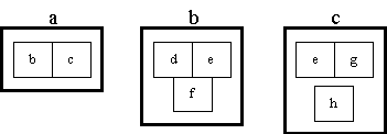
Each diagram in a POSD model redeems promises in other (higher level) diagrams and makes promises that are redeemed by other (lower level) diagrams. Hence the diagrams of a model can be thought of as being organised in a directed graph.
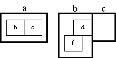
The designer can use a diagram such as the right hand diagram below:
or the right hand diagram below:
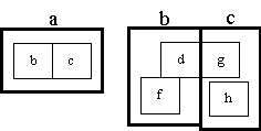
to delegate redemption of a promise to other (lower level) diagrams. The first diagram states that the interaction between systems, b and c, is achieved by an interaction between system, d, (a component of system, b) and system, c. The second diagram states that the interaction between systems, b and c, is achieved by an interaction between system, d, (a component of system, b) and system, g, (a component of system, c).
However diagrams like this can become complicated. It is often possible to produce useful models without this extra complication, as is demonstrated in some of the POSD examples
The interaction between systems, b and c, is achieved in section 2.5 by a component system, e, shared between systems, b and c. In section 2.6 it is achieved by an interaction between components of systems, b and c. This interaction will in its turn need to be achieved either by a (lower level) shared component or by a (lower level) interaction. Ultimately (possibly many levels down) there must be a shared component to realise the interaction between systems, b and c. Here, even a simple interaction mechanism, such as a procedure call or a message passed in an object oriented language, needs to be thought of as a shared component.
A designer may wish to provide alternative structures for a system:
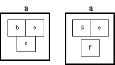
This is allowed in POSD. However the inner structure in each alternative must be capable of all of the behaviour of the outer structure (system, a). In particular the inner structure of each alternative must be capable of all of the interactions required of system, a, and therefore must contain all the shared components required to achieve these interactions. It may be capable of behaviour (including interactions) well beyond those of system, a.
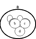
Sometimes a system is composed from a set of components which have similar structure. This is represented in POSD by shading.

The members of the set of systems, b, are distinguished from each other by a suffix, giving b-1, b-2, b-3, etc. Their components must inherit this suffix. Similarly for the set of systems, c.
The above diagram should be interpreted in the weakest possible way. It should be read as
Section 2.2 stated that other shapes are acceptable as well as rectangles. Hence the diagram above could be replaced with:
In the diagrams above, shapes touching means that the shapes represent systems that interact with each other. However suppose a system is composed from four component systems each of which interacts with the other three. This is topologically impossible to represent with touching rectangles (touching at a point does not count). The following notation is permissible as an alternative to deal with this problem:
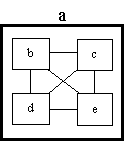
Two rectangles (or other shapes) joined by an unnamed line means the same as two rectangles touching. Both mean that the systems represented by the rectangles interact with each other. It might be thought that the topological difficulties described above occur very frequently and that the form of the POSD notation used in the above diagram should be used for all problems. In practice, the notation with touching rectangles proves quite adequate for most problems as is demonstrated in the POSD examples.
Section 2.3 stated that the composition of systems represented by a diagram's inner structure must be capable of achieving all of the behaviour of the system represented by its outer structure. It can be capable of more behaviour. Given this rule it is possible to be confidant that, as a structural model of a system develops down through many levels, one always knows that the lower level model is capable of all of the behaviour in the higher level models and possibly more.
The rule in section 2.13 means that an interaction appearing in a high level diagram is always achieved by lower level diagrams. However the opposite is not true. The lack of an interaction between two systems in a higher level diagram does not stop lower level diagrams introducing an interaction (by means of a chain of lower level interactions). It may be necessary to introduce notation to indicate definite lack of an interaction where this needs to be preserved. Such rules would need to be respected by the mechanism described in section 2.13. However this is not in the current POSD notation.
The facts that a system, a, interacts with (and thereby affects the behaviour) of a system, b, and the system, b, interacts with (and thereby affects the behaviour) of a system, c, does not mean that the system, a, interacts with (and thereby affects the behaviour) of the system, c - for instance b might have two component systems, d and e, such that d interacts with a, e interacts with c, but d and e do not interact. In other words interaction, considered as a relation, is not transitive. The designer when redeeming promises must not assume transitivity.
last revision: 21st June 1997